Detroit Fault Codes SPN 84/FMI 2 – GHG14


| Description | Vehicle Speed Signal Drops out |
|---|---|
| Monitored Parameter | Vehicle Speed Sensor (VSS) |
| Typical Enabling Conditions | RPM greater than 1200, Torque Demand On |
| Monitor Sequence | None |
| Execution Frequency | Continuous when enabling conditions met |
| Typical Duration | 10 Seconds |
| Dash Lamps | None |
| Engine Reaction | None |
| Verification | RPM greater than 1200, Torque Demand On |
Check as follows:
1. Are there any battery faults (SPN 168/FMI any) or Controller Area Network (CAN) faults (SPN 625/FMI any) present?
1.1. Yes; repair those faults first.
1.2. No; Go to step 2.
2. Has the Common Powertrain Controller (CPC) been recently reprogrammed?
2.1. Yes; ensure the VSS parameters are configured correctly for the vehicle application. If OK, Go to step 3.
2.2. No; Go to step 3.
3. Disconnect the VSS harness connector. Refer to Original Equipment Manufacturer (OEM) literature for location.
4. Inspect the VSS harness connector for bent, spread, or corroded pins. Is any pin damage found?
4.1. Yes; repair as necessary. Verify repairs.
4.2. No; Go to step 5.
5. Is the vehicle equipped with a Hall Effect sensor? Refer to OEM literature for application.
5.1. Yes; Go to step 6.
5.2. No; Go to step 10.
6. Turn the ignition ON (key ON, engine OFF).
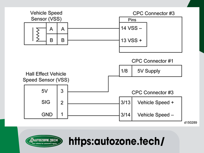
7. Measure the voltage between pin 3 of the VSS harness connector and ground. Is the voltage greater than 4.5 volts?
7.1. Yes; Go to step 10.
7.2. No; Go to step 8.
8. Disconnect CPC #3 connector.
9. Measure the voltage between pin 8 of the CPC #1 connector component side and ground. Is the voltage greater than 4.5 volts?
9.1. Yes; repair wire between pin 8 of the CPC #1 harness connector and pin 3 of the VSS harness connector. Verify repairs.
9.2. No; replace the CPC. Refer to OEM literature.
10. Turn the ignition OFF (key OFF, engine OFF).
11. Disconnect CPC #3 connector.
12. Measure the resistance between pins 13 and 14 of the CPC #3 harness connector. Is resistance greater than 10K ohms?
12.1. Yes; Go to step 13.
12.2. No; repair short between pins 13 and 14 of the CPC #3 harness connector to the VSS harness connector. Verify repairs.
13. Measure the resistance between pin 13 of the CPC #3 harness connector and the VSS + harness connector. Is resistance less than 5 ohms?
13.1. Yes; Go to step 14.
13.2. No; repair wire between pin 13 of the CPC #3 connector and the VSS + harness connector. Verify repairs.
14. Measure the resistance between pin 14 of the CPC #3 harness connector and the VSS – harness connector. Is resistance less than 5 ohms?
14.1. Yes; refer to OEM literature for VSS sensor and sensor wheel diagnostics.
14.2. No; repair wire between pin 14 of the CPC #3 harness connector and the VSS – harness connector. Verify repairs.
AutoZone Tech
- Whatsapp: + 84 899 401 401
- Email: info@dhtauto.com
- Zalo: +84 899 401 401
- Facebook: DHTAuto
- Youtube:DHT AUTO
