Detroit Fault Codes SPN 51/FMI 4 – EPA07 – EPA10 – GHG14


| Description | This Fault Code Sets When There Is an open On The Intake Throttle Valve Circuit |
|---|---|
| Monitored Parameter | Intake Air Throttle |
| Typical Enabling Conditions | Key On |
| Monitor Sequence | None |
| Execution Frequency | Always Enabled |
| Typical Duration | 2 Seconds |
| Dash Lamps | MIL, CEL |
| Engine Reaction | Derate 10% |
| Verification | Engine Idle (1 minute) |
Check as follows:
1. Connect DiagnosticLink® .
2. Turn the ignition ON (key ON, engine OFF).
3. Check for multiple fault codes. Is fault code SPN 3509 FMI 4 also present?
3.1. Yes; diagnose fault code SPN 3509/FMI 4.
3.2. No; Go to step 4.
4. Turn the ignition off.
5. Disconnect and inspect the ITV electrical connector. Is there damage or corrosion present?
5.1. Yes; repair as necessary.
5.2. No; Go to step 6.
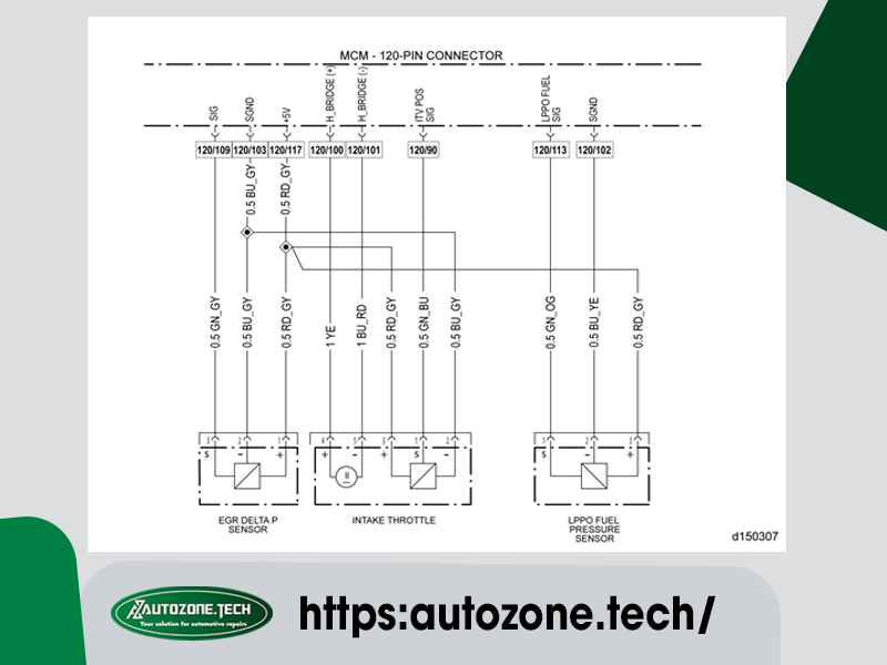
6. Measure the resistance across pins 2 and 3, component side, of the ITV motor connector. Is the resistance less than 10 ohms?
6.1. Yes; Go to step 7.
6.2. No; replace the ITV. Refer to section “Removal of the Intake Throttle Valve and Adaptor” . Verify repair.
7. Measure the resistance across pins 1 and 2, component side, of the ITV motor connector. Is the resistance less than 10 ohms?
7.1. If resistance is greater than 5 ohms, repair open circuit between pin 90 of the MCM 120-pin connector and pin 1 of the ITV connector.
7.2. If resistance is less than 5 ohms, replace the ITV.
8. Turn the ignition ON.
9. Measure the voltage between pin 2 and pin 3 of the ITV electrical connector harness side. Is the voltage between 4.5 and 5.5 volts?
9.1. Yes; Go to step 10.
9.2. No; Go to step 13.
10. Turn the ignition OFF.
11. Disconnect and inspect the MCM 120-pin electrical connector. Is there damage or corrosion present?
11.1. Yes; repair as necessary.
11.2. No; Go to step 9.
12. Measure resistance between pin 1 of the ITV electrical connector harness side and pin 90 of the 120-pin MCM electrical connector harness side. Is the resistance less than 5 ohms?
12.1. Yes; replace the MCM. Refer to section “Removal of the Motor Control Module” .
12.2. No; repair the circuit between pin 1 of the ITV electrical connector harness side and pin 90 of the 120- pin MCM electrical connector harness side.
13. Measure the voltage between pin 3 and ground. Is the voltage between 4.5 and 5.5 volts?
13.1. Yes; repair the circuit between pin 2 of the ITV electrical connector harness side and the splice.
13.2. No; repair the circuit between pin 3 of the ITV electrical connector harness side and the splice.
AutoZone Tech
- Whatsapp: + 84 899 401 401
- Email: info@dhtauto.com
- Zalo: +84 899 401 401
- Facebook: DHTAuto
- Youtube:DHT AUTO
