Detroit Fault Codes SPN 84/FMI 21 – GHG14


| Description | Vehicle Speed Sensor Rationality |
|---|---|
| Monitored Parameter | Vehicle Speed Sensor (VSS) |
| Typical Enabling Conditions | RPM greater than 1500, Torque Demand On |
| Monitor Sequence | None |
| Execution Frequency | Continuous when enabling conditions met |
| Typical Duration | 10 Seconds |
| Dash Lamps | MIL |
| Engine Reaction | None |
| Verification | RPM greater than 1500, Torque Demand On |
Check as follows:
1. Connect DiagnosticLink™.
2. Turn the ignition ON (key ON, engine OFF).
3. Has the Common Powertrain Controller (CPC) been recently reprogrammed?
3.1. Yes; ensure the VSS parameters are configured correctly for the vehicle application. If OK, Go to step 4.
3.2. No;Go to step 4.
4. Turn the ignition OFF.
5. VSS programming options are either hardwired or transmitted via J1939. Is the VSS hardwired?
5.1. Yes; Go to step 6.
5.2. No; refer to the Application and Installation Manual for the correct parameter configuration. If configuration is correct, refer to Original Equipment Manufacturer (OEM) material for J1939 VSS troubleshooting.
6. Disconnect the VSS harness connector. Refer to OEM literature for location.
7. Inspect the VSS harness connector for bent, spread, or corroded pins. Is any damage found?
7.1. Yes; repair as necessary. Verify repairs.
7.2. No; Go to step 8.
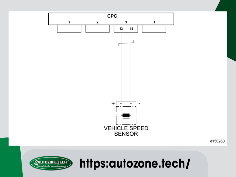
8. Disconnect CPC connector #3.
9. Measure the resistance between pins 13 and 14 of the CPC connector #3. Is the resistance greater than 10K ohms?
9.1. Yes; Go to step 10.
9.2. No; repair short between pins 13 and 14 of the CPC connector #3 and the VSS connector. Verify repairs.
10. Measure the resistance between pin 13 of the CPC connector #3 and battery ground. Is the resistance greater than 10K ohms?
10.1. Yes; Go to step 11.
10.2. No; repair the short to ground between pin 13 of the CPC connector #3 and the VSS+ harness connection. Verify repairs.
11. Measure the resistance between pin 14 of the CPC connector #3 and battery ground. Is the resistance greater than 10K ohms?
11.1. Yes; Go to step 12.
11.2. No; repair the short to ground between pin 14 of the CPC connector #3 and the VSS- connector. Verify repairs.
12. Measure the resistance between pin 13 of the CPC connector #3 and the VSS+ harness connection. Is the resistance less than five ohms?
12.1. Yes; Go to step 13.
12.2. No; repair the wire between pin 13 of the CPC connector #3 and the VSS+ harness connection. Verify repairs.
13. Measure the resistance between pin 14 of the CPC connector #3 and the VSS- harness connection. Is the resistance less than five ohms?
13.1. Yes; refer to OEM literature for VSS sensor diagnostics.
13.2. No; repair the wire between pin 14 of the CPC connector #3 and the VSS- harness connection. Verify repairs.
AutoZone Tech
- Whatsapp: + 84 899 401 401
- Email: info@dhtauto.com
- Zalo: +84 899 401 401
- Facebook: DHTAuto
- Youtube:DHT AUTO
