Detroit Fault Codes SPN 91/FMI 7 – EPA10 – GHG14


| Description | Idle Position not reached 20 Minutes after Ignition on. |
|---|---|
| Monitored Parameter | Pedal Position |
| Typical Enabling Conditions | Always on |
| Monitor Sequence | None |
| Execution Frequency | Continuous when enabling conditions met |
| Typical Duration | 2 Seconds |
| Dash Lamps | None |
| Engine Reaction | None |
| Verification | Key Cycle - Ignition ON |
Check as follows:
1. Turn the ignition ON (key ON, engine OFF).
2. Connect DiagnosticLink® ; are any other fault codes active?
1. Yes; troubleshoot any other faults first.
2. No; Go to step 3.
3. Using DiagnosticLink, monitor PWM Pedal Signal GAS1 and PWM Pedal Signal GAS2 under the Instrumentation/Chart tab.
4. Cycle Accelerator Pedal (AP) slowly several times with a full sweep from top to bottom of travel. Does voltage sweep smoothly in relation to pedal travel?
4.1. Yes; Go to step 5.
4.2. No; replace the AP. Refer to Original Equipment Manufacturer (OEM) literature.
5. Clear codes and cycle ignition off.
6. Turn the ignition ON (key ON, engine OFF).
7. Does the code return?
7.1. Yes; replace the AP, clear codes and verify repairs. Refer to Original Equipment Manufacturer (OEM) literature.
7.2. No;Go to step 8.
8. Gently wiggle pedal and harness connector to simulate road vibration. Go to step 9.
NOTE: Do not disconnect the Accelerator Pedal (AP) connector at this time.
NOTICE:
Do not tap on AP with metal object or tool as this may damage component.
NOTICE:
A second technician may be required to monitor values during wiggle testing.
9. While performing wiggle test, monitor PWM Pedal Signal GAS1 and PWM Pedal Signal GAS2 under the DiagnosticLink Instrumentation/Chart tab.
10. Cycle Accelerator Pedal (AP) slowly several times with a full sweep from top to bottom of travel. Do the percentages sweep smoothly in relation to pedal travel?
10.1. Yes; Go to step 11.
10.2. No; Isolate that section of harness and inspect for wire chaffing, corrosion, improper connections or physical damage and repair as necessary . Verify repair.
11. Disconnect the Accelerator Pedal (AP).
12. Inspect the AP and harness side connectors for signs of damaged, bent, spread, corroded or unseated (pushed out) pins and signs of moisture in the connector or wire damage near the connector. Is any damage found?
12.1. Yes; repair as necessary. Verify repair.
12.2. No; Reconnect the AP. Go to step 13.
13. Gently wiggle CPC harness connectors to simulate road vibration. Go to step 14.
14. While performing wiggle test , monitor PWM Pedal Signal GAS1 and PWM Pedal Signal GAS2 under the DiagnosticLink Instrumentation/Chart tab. Go to step 15.
15. Cycle Accelerator Pedal (AP) slowly several times with a full sweep from top to bottom of travel. Do the percentages sweep smoothly in relation to pedal travel?
15.1. Yes; Go to step 16.
15.2. No; Isolate that section of harness and inspect for wire chaffing, corrosion, improper connections or physical damage and repair as necessary . Verify repair.
16. Disconnect the CPC #1 connector.
17. Disconnect the CPC #3 connector.
18. Disconnect the CPC #4 connector.
19. Inspect the CPC and the harness connectors for signs of damaged, bent, spread, corroded or unseated (pushed out) pins and signs of moisture in the connector or wire damage near the connectors. Is any damage found?
19.1. Yes; repair as necessary. Verify repair.
19.2. No; replace the AP, clear codes and verify repair. Refer to Original Equipment Manufacturer (OEM) literature. Verify repair.
AutoZone Tech
- Whatsapp: + 84 899 401 401
- Email: info@dhtauto.com
- Zalo: +84 899 401 401
- Facebook: DHTAuto
- Youtube:DHT AUTO
Description:
| Sensor Connector and Pinout | ||||
|---|---|---|---|---|
| Function | CPC pinout | Connector Pinout | Comments | Harness Connector Body |
| APS1 | 1/7 | A | SENSOR 1 | 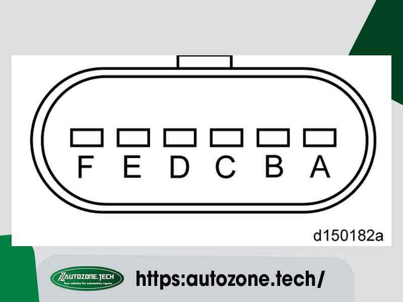 |
| GND1 | 1/4 | B | APS1 GND | |
| VCC1 (+5V) | 1/8 | C | APS1 Power Supply | |
| VCC2 (+5V) | 3/3 | D | APS2 Power Supply | |
| GND2 | 3/2 | E | APS2 GND | |
| APS2 | 4/14 | F | SENSOR 2 | Harness Connector and Seal (P/N: 12066317) Terminal Female (P/N: 12103881) |
