Detroit Fault Codes SPN 91/FMI 8 – EPA10 – GHG14


| Description | Channel 1 Sensor Signal failed (high or low) |
|---|---|
| Monitored Parameter | GAS1 |
| Typical Enabling Conditions | Always on |
| Monitor Sequence | None |
| Execution Frequency | Continuous when enabling conditions met |
| Typical Duration | 2 Seconds |
| Dash Lamps | CEL |
| Engine Reaction | None |
| Verification | Key Cycle - Ignition ON |
Check as follows:
1. Disconnect the Accelerator Pedal (AP).
2. Inspect the AP and harness side connectors for signs of damaged, bent, spread, corroded or unseated (pushed out) pins and signs of moisture in the connector or wire damage near the connector. Is any damage found?
1. Yes; repair as necessary. Verify repair.
2. No; Go to step 3.
3. Turn the ignition ON (key ON, engine OFF).
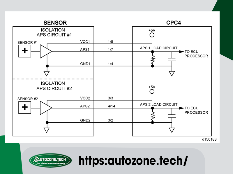
| Sensor Connector and Pinout | ||||
|---|---|---|---|---|
| Function | CPC pinout | Connector Pinout | Comments | Harness Connector Body |
| APS1 | 1/7 | A | SENSOR 1 | 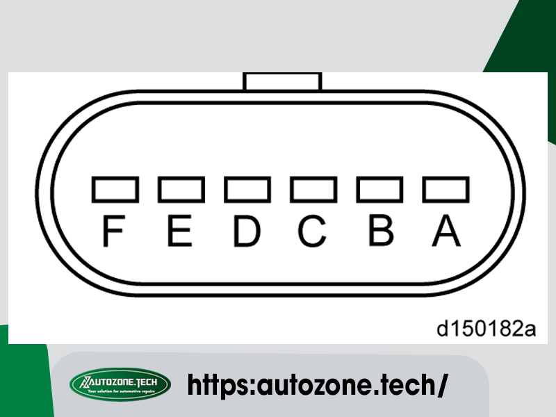 |
| GND1 | 1/4 | B | APS1 GND | |
| VCC1 (+5V) | 1/8 | C | APS1 Power Supply | |
| VCC2 (+5V) | 3/3 | D | APS2 Power Supply | |
| GND2 | 3/2 | E | APS2 GND | |
| APS2 | 4/14 | F | SENSOR 2 | Harness Connector and Seal (P/N: 12066317) Terminal Female (P/N: 12103881) |
4. Measure the voltage between pin C and B of the AP harness connector. Is the voltage between 4.5 and 5.5 volts?
4.1. Yes; Go to step 6.
4.2. No; Go to step 5.
5. Measure the voltage between pin C of the AP harness connector and ground. Is the voltage between 4.5 and 5.5 volts?
5.1. Yes: repair the open circuit between pin B of the AP harness connector and pin 4 of the Common Powertrain Controller (CPC) #1 connector. Verify repair.
5.2. No; repair the circuit between pin C of the AP harness connector and pin 8 of the CPC #1 connector. Verify repair.
6. Measure the voltage between pin A of the AP harness connector and ground. Is any voltage present?
6.1. Yes; repair the short to power between pin A of the AP harness connector and pin 7 of the CPC #1 connector. Verify repair.
6.2. No; Go to step 7.
7. Turn the ignition OFF.
8. Disconnect the CPC #1 connector.
9. Inspect the CPC and the harness connector for signs of damaged, bent, spread, corroded or unseated (pushed out) pins and signs of moisture in the connector or wire damage near the connector. Is any damage found?
9.1. Yes; repair as necessary. Verify repair.
9.2. No; Go to step 10.
10. Measure the resistance between pin A of the AP harness connector and pin 7 of the CPC #1 connector. Is the less than 5 ohms?
10.1. Yes; Go to step 11.
10.2. No; repair the open circuit between pin A of the AP harness connector and pin 7 of the CPC #1 connector. Verify repair.
11. Measure the resistance between pin A of the AP harness connector and ground. Is the resistance greater than 10K ohms?
11.1. Yes; replace the AP. Verify repair.
11.2. No; repair the shorted circuit between pin A of the AP harness connector and pin 7 of the CPC #1 connector.
AutoZone Tech
- Whatsapp: + 84 899 401 401
- Email: info@dhtauto.com
- Zalo: +84 899 401 401
- Facebook: DHTAuto
- Youtube:DHT AUTO
